
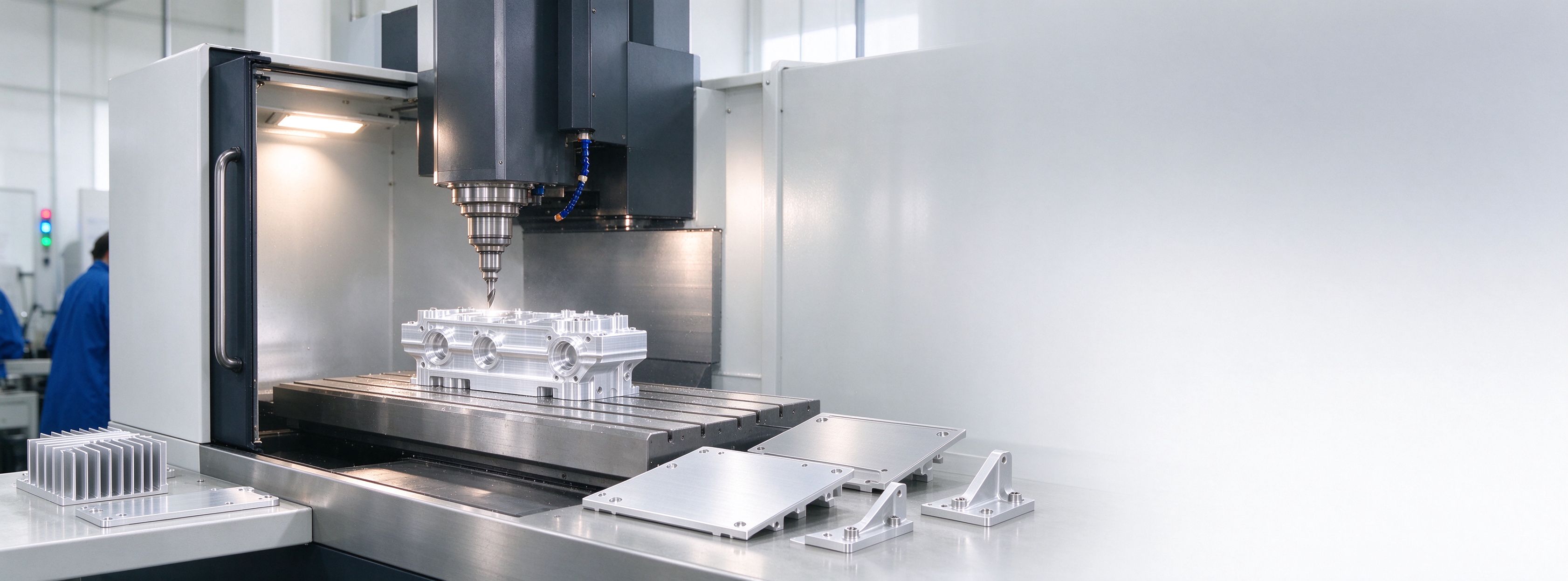
How to Design Internal Corners and Undercuts for Cost-Effective CNC Milling
-
Eren
- 12th November 2026

Optimizing Internal Corners and Undercut Features for Cost-Effective CNC Milling
For creating precision milled components through CNC technology, it is essential to consider the trade-off between tolerances and efficiency. Here is a guide about DFMA considerations related to internal radii and undercuts.
Introduction to DFM Strategies for CNC Milling Internal Corners and Undercuts
The internal features determine the manufacturing overhead. One of the main objectives of design engineers is the reduction of expensive Electrical Discharge Machining (EDM) secondary operations. Where there are sharp internal corners or profiles that disregard the standard end mill radius and CNC machining tool reach, sinker EDM or additional setups become necessary. Adopting DFM for CNC milling early on will enable the engineers to maximize internal corner radii in CNC machining, remove CNC machining undercuts bottlenecks, take advantage of T-slot cutters, and reduce unit cost.
Precision Manufacturing Capabilities at Rejin CNC
As an exact-precision CNC milling manufacturer in Dongguan, China, Rejin CNC offers 20+ years of machining experience for international OEM projects.
- Vertical Infrastructure: Producing on 200+ CNC machines—3-, 4-, and 5-axis VMCs as well as turn-mill machines—to produce from prototypes to over 50,000 units per month.
- Quality System Certification: Certified according to ISO 9001:2015 and IATF 16949, employing CMM 3D measurement to control tolerances down to ±0.005 mm.
- DFM Analysis PerformedBy Engineer: CAD models undergo DFM analysis for CNC milling review by an experienced CAM engineer within 24 hours, determining tool reach restrictions, CNC pocket corner radius restrictions, and cost factors.
- Internal Finishing Services & Worldwide Coverage: Offering finishing services including anodizing, bead blasting, and passivation for audio components, 3C, EV, robots, and thermal solutions for 60+ countries.
Critical Guidelines for CNC Milling Internal Corner Radius Design
Selecting corner geometry is the most effective way to cut cycle time and chatter. The following rules establish standard parameters for internal pocket corners.

Engineering Tool Accessibility and Standard End Mill Radius Selection
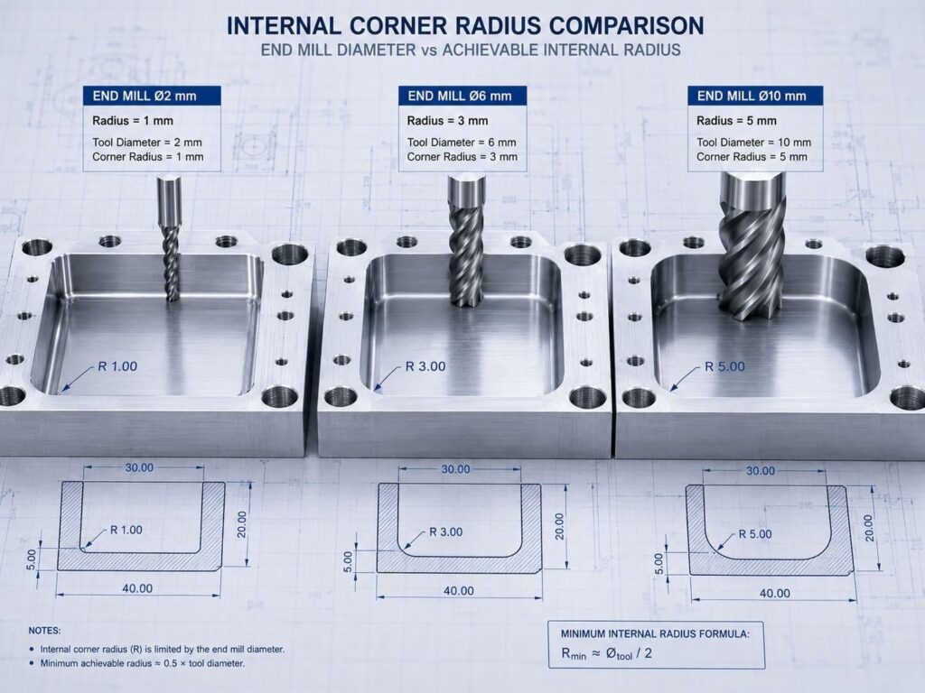
Internal angles that are at 90 degrees cannot be cut using rotary tools. Knowledge of CNC machine tool accessibility is based on understanding tool geometry, since each end mill leaves a radius equal to half of its diameter.
- Tool Standard Size: Make internal corner radius sizes of internal pockets based on the standard radius size of the end mill (1.5 mm, 2.0 mm, 3.0 mm, and 6.0 mm) and not the nonstandard radius size of 2.3 mm.
- Clearance Ratio of Cutter (1.15× rule): Provide an internal corner radius of the CNC mill at least 15% larger than the cutter radius size. For a 6 mm cutter, an internal corner radius of 3.5 mm is appropriate to prevent chatter.
- Tool Engagement Control: Once the cutter enters a perfectly fitted corner, there is engagement from 90 degrees to 180 degrees, resulting in chatter.
Deep Pocket CNC Milling and Depth-to-Radius Ratios
In deep-pocket CNC milling, tool deflection is introduced as tool length relative to cutter diameter.
- Maximum Depth Ratio (3:1 ratio standard): Maintain pocket depth less than 3 times the cutter diameter. For a pocket depth of 30 mm, use a 10 mm end mill and specify an internal corner radius of at least 5.75 mm to meet the 15% clearance rule.
- Extended Reach Restrictions (ratio up to 5:1): Pockets greater than 4:1 have reduced feed rate, leading to increased machining time up to 150%. If deep pockets are needed, step profile or increase corner radius for deeper z-level.
- Bottom Floor Fillets: Apply bottom floor fillets with a radius of 0.5 mm to 1.5 mm where vertical walls meet the bottom, using bull-nose end mills to improve tool life.
Implementing Dogbone and T-Bone Relief Cuts to Eliminate EDM
When a mating rectangular pin or circuit board must seat square into a milled pocket, corner relief features provide a cost-effective solution.
Design Principles for Dogbone Corner Relief CNC Features
The employment of dogbone corner relief allows a cutter to drill out the corner vertex of a part without any need for sinker EDM machining in mating square corners.
- Relief Hole Sizing: Selecting a relief hole size equivalent to or even larger than the primary cutter is advised. In case of a 4mm end mill cutter, a 4.1 mm hole size for the dogbone will completely relieve square corners.
- Requirements for Positioning Vertex: The vertex point must be positioned on the 45-degree angle bisector to ensure proper mating of the pin after cutting.
- Protecting Structural Wall Integrity: Avoid oversized relief holes since they may compromise the overall structure of thin-walled enclosures.
T-Bone Relief CNC Machining for Aesthetic and Assembly Optimization
When dogbone reliefs appear aesthetically unsatisfactory on exterior surfaces, T-bone relief CNC machining provides the optimal solution.
- Single Wall Extension Shape: T-bone relief extends into one wall instead of extending along the bisector line, making the notch invisible from the outside wall.
- Efficiency of Toolpath: T-bone relief is machined in accordance with CNC milling guidelines during the profiling process. The cutter enters one wall at the tool radius and exits without decelerating.
- Criteria for Application: T-bone relief machining is suggested for 3C electronics housing parts and audio interface plates when top surface appearance is crucial.
Advanced Strategies for CNC Undercut Design and Tooling
Undercuts are recessed features unreachable by vertical end mills from top-down setups. Adhering to CNC undercut design rules avoids expensive multi-axis re-indexing.

Undercut Machining Design Guidelines Using T-Slot and Keyseat Cutters
Snap ring grooves and seal grooves are two traditional examples where the undercut machining design criteria are applicable.
- Tool Clearance Requirements: Undercuts should be provided considering the T-slot or keyseat cutters available. Make sure that the undercut radial depth is less than the neck clearance of the cutter.
- Standard Slot Heights: Specify undercut slot heights that match available cutter thicknesses, such as 1.5 mm, 2.0 mm, 3.0 mm, or 6.0 mm. Other depths require a special grind, resulting in higher costs.
- Bore Entrance Clearance: The undercut radial depths should remain relatively small with respect to the total entrance hole to avoid interference with the cutter head.
Spherical and Side-Wall Undercut Feature Optimization
Contoured internal undercuts may require custom ball/lollipop cutters or 5-axis capability.
- Clearance Requirements for Lollipop Cutters: Ensure compatibility between radii and standard ball cutter shanks while designing 3D internal undercuts to prevent collision problems with the tool post.
- Multi-Axis Machining Helps Save Setups: In case of undercuts on different sides, 5-axis indexing helps reduce cumulative datum errors, thereby enabling a one-setup machining operation.
- Integration of Deburring in Process Flow: Provide 0.2 mm × 45° chamfers in the design file for internal undercut edges. CNC deburring can save manual effort up to 80%.
Practical Applications and Rejin CNC Engineering Validation
Applying proven DFM principles yields tangible savings across OEM manufacturing programs.

Case Study 1: High-Volume Aluminum Audio Control Panels
A high-end audio equipment maker was in need of custom CNC-machined 6063-T5 aluminum audio control panels, featuring 12 display cutouts in anodized finish.
- Early Stages Bottleneck: The drawing called for sharp 0.5 mm internal corners inside 15 mm cutouts, making it impossible to machine the part and resulting in expensive sinker EDM machining with a 4-week lead time.
- Rejin CNC DFM: Rejin CNC design engineering specialists advised changing the corner radius from 0.5 mm to 2.5 mm, thus enabling machining all cutouts with one operation of a 4 mm end mill.
- Hard Facts: 38% reduction in machining time, 26% reduction in unit cost, production volume reached 80K+ units/year with fewer than 15 defects PPM.
Case Study 2: Precision EV Fluid Connector Housings
The manufacture of an EV subsystem required AISI 304 stainless steel connector assemblies with internal retaining ring undercuts and tight-tolerance thread shoulders.
- Design Constraint: The initial design was a non-standard 1.75 mm internal snap ring groove located 25 mm into a Ø18 mm bore, resulting in chatter and broken tools.
- Rejin CNC DFM Solution: Rejin CNC optimized the undercut to a standard 2.0 mm and altered the entry chamfer, allowing standard T-slot cutters to operate at optimal feed rates.
- Results: Tool life was extended five times, bore cycle time was reduced by 42%, and CMM inspection confirmed tight datum alignment for a 15,000-unit production run.
Streamlining Production with Cost-Effective CNC Milling Design
Implementing clear design rules ensures seamless progression from prototyping to volume production.
Essential Checklist for Cost-Effective CNC Milling Design
Before releasing CAD models for production quoting, verify your design against these cost-effective CNC milling design engineering standards:
Internal Radii: Are all pocket corner radii at least 15% larger than standard cutter radii?
- Pocket Depths: Is pocket depth limited to a 3:1 depth-to-diameter ratio wherever possible?
- Square Assembly Reliefs: Are dogbone corner relief CNC or T-bone relief CNC machining features incorporated for mating square components?
- Undercut Standardizing: Do undercut slot heights match standard T-slot cutter thicknesses?
- Datum Alignment: Are tight tolerances specified only where functionally necessary (e.g., ±0.005 mm on bearing bores, ±0.05 mm on non-mating surfaces)?
Partner with Rejin CNC for Expert DFM and Precision Manufacturing
Transforming complex drawings into cost-effective parts requires an experienced partner. At Rejin CNC, CAM engineers review CAD models upfront to eliminate cost drivers before cutting metal.
- 24-Hour DFM & Fast Quote: Receive a technical DFM report and competitive quotation within 1 business day.
- Prototyping to Mass Production: From 1-piece prototypes delivered in 3-7 days up to 50,000+ production runs.
- NDA & IP Protection: Your CAD files remain strictly confidential on our internal network.
Ready to eliminate unnecessary EDM costs and optimize your CNC milled components? Contact Rejin CNC today at info@rejincnc.com or upload your STEP/IGES files via our website to receive a free 24-hour DFM evaluation and quotation.
FAQ
Q: Why is it more cost-effective to increase the internal corner radius?
A: By increasing the internal corner radius, machine shops can use bigger and stiffer end mills running at faster feed rates. An internal corner radius 15% larger than the cutter radius allows for continuous tool paths without stopping in the corners, eliminating any chatter.
Q: When should design engineers choose dogbone relief cuts over T-bone relief cuts?
A: Dogbone relief cuts are ideal for structural components where equal clearance is required along both adjacent walls and aesthetics are secondary. T-bone relief cuts extend into one wall, hiding the notch beneath a flange, making them superior for visible 3C and audio hardware.
Q: What are the main tooling constraints to consider when designing internal undercuts?
A: Key constraints include cutter neck clearance diameter, slot height matching standard cutter thicknesses, and entry bore clearance. Undercut radial depths must remain shallow enough so the cutter head enters the bore without colliding with sidewalls.
Q: Can CNC milling eliminate secondary EDM operations entirely for square pocket features?
A: Yes, by integrating dogbone or T-bone corner reliefs into CAD designs, standard round end mills clear interfering material. This allows mating square pins or PCBs to seat fully flush, eliminating time-consuming and expensive sinker EDM secondary operations.
Recent Posts

Thermal Management Design: Why CNC Machined Heatsinks Outperform Extrusions

Low-Volume CNC Machining: Sourcing for Prototyping Rapid Hardware

How to Manufacture Aluminum iPad Hubs & Docks Without Overheating
RELATED PRODUCTS
Parts We Machine Every Day
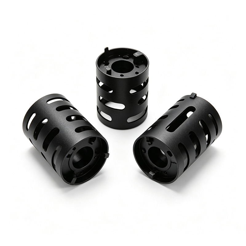
CNC Machined Aluminum Heat Sink Sleeves & Motor Cooling Cages
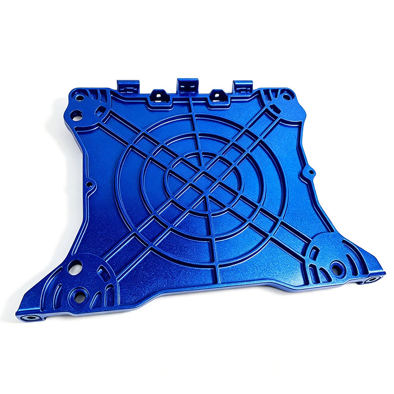
CNC Aluminum Automotive Brackets & Lightweight Structural Links
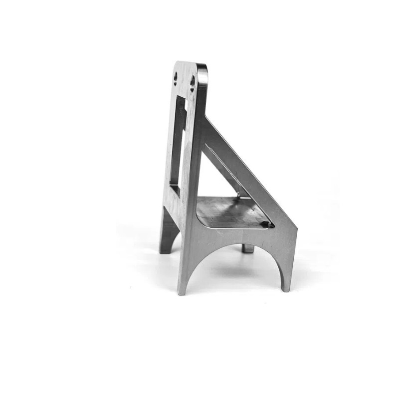
CNC Machined 304 Stainless Steel Support Brackets for UAV Avionics & Sensor Mounts

CNC 5-Axis Aluminum Tri-Arm Structural Hub for UAV Airframes
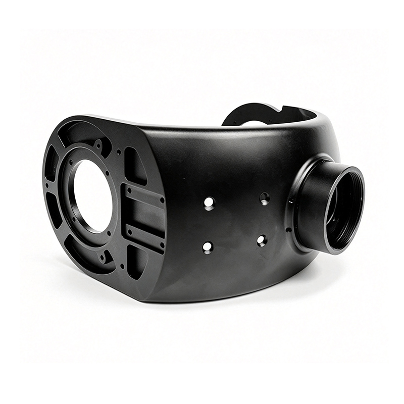
CNC UAV Camera Gimbal Brackets & Yoke Frames | 6061 Aluminum
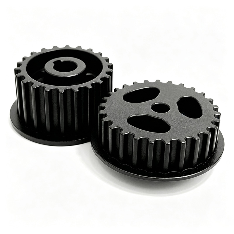
Custom CNC Aluminum Timing Belt Pulleys with Keyway Bore & Lightening Holes for Robot Drives

Custom CNC Stainless Steel Flanged Hub Housings & Bearing Adapter Brackets for Robot Joints

Custom CNC Brass Bulkhead Hose Barb Fittings (M8) Elbow & Straight for UAV Fluid Reservoirs
SIMPLE PROCESS
What Happens After You Click Send?
Your message lands directly with our senior engineers — instantly acknowledged.
We study your requirements and propose a workable solution with material & process options.
Detailed quotation with specs, options and lead time — no hidden fees.
Approve the sample, then we mass-produce with full QC and on-time shipping.
WhatsApp: +86 13790500374
Email: info@rejincnc.com

Scan this QR code with your WeChat app to add us as a contact — send drawings, get quotes within 24 hours and chat with our engineers directly.
Custom Quote Within 24 Hours
Your CAD files are kept strictly confidential. Quotation within 24 hours.